Visual Node Graphs & Node Reference Manual
Unilighter features a powerful visual programming engine called Node Graphs. They let you build custom lighting logic, audio-reactive effects, procedural sequences, and parameter macros using visual wiring instead of writing code.
🧠 Concept & Signal Processing Architecture
A Node Graph is a continuous signal processing chain where data flows from left to right:
[ Input Node ] ──(Data Wire)──> [ Process Node ] ──(Data Wire)──> [ Output Node ]
(Audio / LFO / Fader) (Math / Sequence / Delay / Gate) (Physical Fixture / Tagged Device)- Real-Time Processing: The graph evaluates in sync with the console frame clock (40+ times per second).
- Live Editing: You can connect, disconnect, or reroute wires dynamically during a show without interrupting the DMX output.
- Scalar & Sequence Data: Ports can carry single numbers (scalars) or ordered numeric arrays (sequences). Sequence-aware nodes process spatial spreads and chasing offsets across multi-fixture tags natively.
🧭 Organizing and Editing the Canvas
The graph editor includes layout tools for keeping large shows readable while they remain live:
- Frame containers group related nodes visually. Select one or more nodes and click Frame Selected to create a frame that fits them, or add a frame from Add Node → Layout → Frame. Drag a frame header to move its children together, use the corner handle to resize it, double-click the title to rename it, and use the color swatch to distinguish sections.
- Reroute points keep long cables tidy without changing the signal. Double-click a cable to insert a reroute at that location. Its compact input and output ports pass Number, Sequence, and Audio data through unchanged.
- Drag a node into a frame to make it a child of that frame. Deleting a frame leaves its children in the graph; deleting the frame and its children together removes the whole group. Copy, paste, and duplicate preserve frame membership and internal connections.
- Connected inputs can be replaced by dragging from the compact port or by using click-to-click connection mode. The active port is highlighted while you choose the other end, and double-clicking a reroute port disconnects it.
- The add-node popup focuses Search nodes automatically on desktop. Type a node name and press Enter to add the first matching result; Escape clears the search first and closes the popup when it is already empty. Selected nodes use a clear outer glow, which helps when working in a dense graph.
These tools change the graph's presentation and wiring only; they do not add processing or interrupt the graph's live output.
⚡ Enabling & Disabling Node Graphs
Each graph has an Enable / Disable switch:
- Enabled: The graph is active and streaming data to fixtures or virtual parameters.
- Disabled: The graph stops evaluating and releases its hold on the fixtures.
- Safety Rule: When using the AI Assistant Panel to restructure a graph, make sure to disable it first to avoid sudden flashes or erratic movements on stage.
📦 Node Graphs as Reusable Functions
Node Graphs run as independent logic blocks in the background:
- You can create multiple graphs per project, handling different tasks (e.g., one for strobe generation, another for a continuous pan/tilt sweep).
- Because they are registered as Functions, you can map them to a Function Widget on your Dashboard to easily toggle them on and off during a live performance.
🔌 Socket Data Types
Nodes use color-coded sockets to indicate the type of data they send and receive:
| Data Type | Value Range | Common Usage |
|---|---|---|
| Number | 0.0 to 1.0 (or 0-255) |
Intensity, speed, math multipliers, angles. |
| Sequence | Numeric array (1–64 elements) | Multi-fixture offsets, wave spreads, step patterns. |
| Number or Sequence | Scalar number or sequence | Polymorphic arithmetic, routing, delay distribution, shared values. |
| Color | RGB / HSL | Passing color values to fixture heads. |
| Trigger | True / False |
Opening gates or toggling states. |
| Vector | 2D Coordinates (X, Y) |
Spatial position for Pan/Tilt. |
| Spectrum | Multi-Band Array | Raw FFT audio data for frequency analysis. |
📚 Node Reference Manual
There are 15 functional nodes divided into Input, Process, and Output categories, plus two layout nodes and modular Subgraphs.
1. Input Nodes (input)
Input nodes sit at the beginning of your graph to generate or capture control signals.
🎙️ Audio Input (AudioNode)
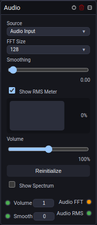
Captures live audio from your system (microphone or line-in) and performs real-time Fast Fourier Transform (FFT) analysis. You can pick the exact audio interface to listen to, adjust the input gain for quiet signals, and add smoothing so the lights don't jitter too aggressively.
It provides a raw Audio FFT output for frequency analysis and an Audio RMS output for overall signal level. The RMS Meter and Spectrum displays can be toggled independently, and the spectrum includes readable frequency and level guides.
Example: Wire Audio FFT into a Frequency Meter Node, then send the selected band's RMS through a Gate Node to the intensity of your wash lights so they pulse to the kick drum.
Read the dedicated Audio Input Node Manual.
🎨 Color (ColorNode)
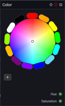
Provides an interactive color wheel right on the canvas. It outputs a standardized color signal that downstream fixtures can understand, regardless of whether the physical light uses RGB, CMY, or a color wheel.
Example: Connect this node's output to a group of moving heads to quickly change the ambient stage color by dragging your mouse around the wheel.
🎚️ Fader / Knob / Dropdown (ValueNode)
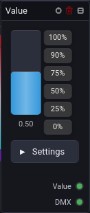
Creates a manual control interface on the canvas. You can configure it to display as a vertical fader, a rotary knob, a dropdown list, or a group of toggle buttons.
- Fader & Knob: Perfect for continuous numerical values. You can specify the exact
Min,Max, andStepsize. - Dropdown & Buttons: Allow you to define explicit text labels mapped to specific numerical values (e.g. "Slow" = 0.2, "Fast" = 0.8).
Example: Add a rotary knob to control the sweep speed of an oscillator, giving the lighting operator a clear visual control to tweak during the show.
🕹️ XY Pad (XYNode)
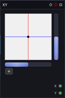
Gives you a 2D touch surface with a crosshair that outputs X (horizontal) and Y (vertical) coordinates.
Example: Wire the X and Y outputs to the Pan and Tilt inputs of a spotlight. This effectively turns the XY Pad into a virtual joystick to manually aim the light across the stage.
🌊 Oscillator (OscillatorNode)
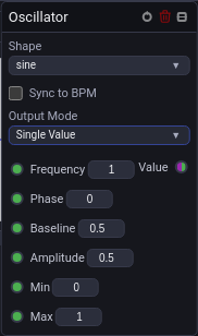
Generates repeating mathematical waves used for continuous motion or chasers. It can run freely in Hertz or lock to the show's master BPM.
- Shapes: Sine, Sawtooth, Square, Impulse, Triangle, Noise.
- Output Mode: Can output a
Single Valuefor unison movement, or aSequencearray (based on aspreadandsequenceLength) to create chasing offsets across multiple fixtures. - BPM Sync: Can sync to fractions from
x16(extremely fast) down to/16(very slow). - Control Sockets: Sequence control inputs (
Frequency,Phase,Spread) remain scalar to produce clean one-dimensional wave series.
Example: Send a slow Sine wave to the Tilt channels of your moving heads to make them slowly sweep up and down in the background.
🌐 Shared Values (SharedValuesNode)
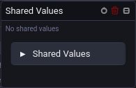
Allows you to read global variables that are shared across your entire project. Shared values support scalar numbers, sequences (number-array), polymorphic Number or Sequence, and audio data.
Example: If you want multiple independent node graphs to react to a single "Master Speed" fader or a shared procedural sequence pattern, you can bind them all to the same Shared Value instead of building a massive, cluttered single graph.
2. Process Nodes (process)
Process nodes manipulate, combine, transform, or filter signals before they reach the fixtures.
➕ Math (MathNode)
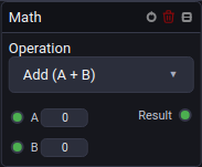
Takes one or two input numbers and performs arithmetic, bounding, range remapping, or custom JavaScript mathematical equations.
MathNode is numeric-polymorphic:
- Scalar Math: When every input is scalar, the result is scalar.
- Sequence Math & Broadcasting: When any input is a sequence, the output is a sequence whose length matches the longest input sequence. Scalar inputs automatically broadcast to all elements, while shorter sequences repeat cyclically. If any connected sequence is empty, the result is an empty sequence.
- Custom Equations: Evaluated per element with variables
a,b,min,max,fromMin,fromMax,toMin,toMax,i(current element index),n(result sequence length), andseq.<name>exposing full normalized input sequences.
Read the dedicated Math & Expression Node Manual.
🔢 Sequence (SequenceNode)
Generates, resizes, and structurally transforms numeric sequences up to 64 elements long. Scalar inputs are automatically treated as single-element sequences. Every operation exposes both the calculated Sequence array and a single Item extracted via the cyclic Item Index input.
Available Operations:
- Manual: Direct editable, reorderable list of numbers saved within the graph.
- Fill: Repeats a single scalar value up to the requested length.
- Range: Produces evenly spaced values between
StartandEnd, inclusive. - Concat: Joins sequences
AandBinto a combined sequence. - Reverse: Flips element order from back to front.
- Rotate: Cyclically shifts elements by a signed integer
Offset. - Resize (Cycle): Truncates or cyclically repeats values to target length (ideal for repeating fixture clusters).
- Resample: Resizes sequence using nearest-neighbor sampling while preserving endpoints.
- Interpolated Resample: Resizes with smooth linear interpolation (ideal for stretching short curves across tag fixture counts).
- Mirror: Symmetrically mirrors elements without duplicating the center (
[a, b, c]becomes[a, b, c, b, a]). - Seeded Shuffle: Deterministic Fisher-Yates shuffle where identical input and seed guarantee reproducible ordering.
⏳ Delay (DelayNode)
A stateful numeric delay line providing a single scalar Value input with two simultaneous outputs:
Delayed: Emits the historical scalar value fromDelaysteps ago.Sequence: Emits a tapped sequence[current, value(-Delay), value(-2*Delay), ...]spanningLengthtaps (1–64). Perfect for driving tagged fixtures with trailing wave offsets.
Clock & History Modes:
- Updates Clock: Advances history on every incoming value change/request delivered to the socket.
- Frames Clock: Samples input once per console frame clock tick, allowing single transients to continue propagating across taps even when input stops updating.
- Warm-Up Modes: Zeros (initializes history with zero) or First Value (primes history with first received sample).
🚪 Gate (GateNode)
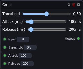
Acts as a dynamic envelope filter and peak trigger with Attack and Release timings.
- Polymorphic Signal Processing: Accepts either a scalar number or a sequence on
Signal In. - Per-Element Envelope State: When fed a sequence, envelope tracking and Attack/Release filtering are maintained independently for each fixture element.
- Scalar Controls:
Threshold,Attack (ms), andRelease (ms)remain scalar for uniform envelope shaping.
Read the dedicated Gate & Envelope Follower Node Manual.
🔀 Router (RouterNode)
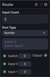
Directs an incoming signal to one of multiple output routes based on a numerical index channel. Supports Number or Sequence (numeric) mode, allowing either single scalars or multi-element sequences to pass through dynamically without truncation.
Read the dedicated Signal Router Node Manual.
📊 Frequency Meter (FrequencyMeterNode)
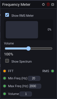
Analyzes the raw audio spectrum and isolates a highly specific frequency band (Min Freq to Max Freq). In Parametric mode, the selected window is highlighted on the spectrum. In Fixed mode, the standard listening bands are highlighted and labeled.
Example: Connect this to the Audio FFT output of an Audio node, dial it in to 40-100 Hz, and route the result to your strobe lights. They will now flash precisely when the sub-bass hits, ignoring the rest of the music.
Read the dedicated Frequency Meter Node Manual.
👥 Group (GroupNode)
Takes an incoming signal and distributes it across physical fixtures, applying intelligent delays, phase spreads, or fan offsets based on stage positioning.
⏱️ BPM & Audio Tempo Clock (BpmNode)

Transforms incoming FFT audio spectrum into a rock-solid musical tempo clock using spectral flux analysis and inter-onset interval (IOI) tracking.
- Autonomous Master Tempo Steering: Enabling Control tempo links the node to Unilighter's central master clock via
changeBpmPreservePhase, smoothly adapting show speed without beat-skipping. - Musical Fractions: Emits clock frequencies in Hertz (
x4,x2,x1,/2,/4,/8) and discrete Boolean downbeat trigger pulses. - Bandpass Transient Isolation: Tunes the detector strictly to kick drum frequencies (
40–200 Hz), filtering out vocals and cymbals.
Read the dedicated BPM & Audio Tempo Node Manual.
3. Output Nodes (output)
Output nodes route processed signals to fixture channels or global parameters.
💡 Device (DeviceNode)
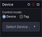
Maps node logic directly to physical fixture parameters or tagged device groups.
- When bound to a tagged device group, feeding a Sequence to a channel socket (such as
DimmerorPan) distributes each array element directly to the corresponding fixture head in the tag.
🎛️ Device Control (DeviceControlNode)
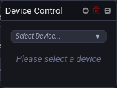
A high-level node for triggering presets, macros, and global parameter overrides across devices.
4. Layout Nodes (layout)
Layout nodes organize the canvas without changing the signal values.
🖼️ Frame (Frame)
A frame is a colored, resizable container for related nodes. Creating one around a selection automatically adds padding and records the selected nodes as its children. Moving the frame moves unselected children with it, while dragging a child into another frame updates its membership. Frames have no input or output sockets.
↪️ Reroute (Reroute)
A reroute point has one input and one output and supports Number, Sequence, and Audio signals. It simply forwards the received value, so it is useful for bending a cable around a node, splitting a complex graph into readable sections, or reconnecting a cable without moving the source and target nodes. Double-click an existing cable to place one automatically at the clicked point.
5. Subgraphs & Function Interface Nodes
Encapsulates complex node chains into reusable, modular building blocks with custom inputs and outputs.
🧱 Group Inputs & Outputs (GroupInputsNode / GroupOutputsNode)

- Group Inputs Node: Declares exposed parameter sockets supporting
Number,Sequence,Number or Sequence,Color,Boolean, andTrigger. - Group Outputs Node: Streams calculated scalars, sequences, or colors back to parent graphs.
- Encapsulated Scope: Internal math equations, delay buffers, and envelope states remain cleanly contained inside the subgraph.
Read the dedicated Subgraphs & Reusable Function Nodes Manual.
⚡ Typical Signal Flow Recipes
# 1. Procedural generative chase across tagged lights
Oscillator (Sequence) ──> Math (Clamp / Map Range) ──> Device (Tag Dimmer)

# 2. Dynamic trailing wave from a single control or fader
Value / Oscillator (Single) ──> Delay (Tapped Sequence) ──> Device (Tag Dimmer)

# 3. Custom curve resampled to match fixture count
Sequence (Manual / Range) ──> Sequence (Interpolated Resample) ──> Device (Tag Pan)