Lesson 1.3: Physical Cabling: Daisy Chains, Adapters & Terminators
Many of the most frustrating DMX problems on a live stage—moving heads twitching, strobes flashing unexpectedly, or the last fixtures in a line dropping out—come back to three basic cabling mistakes:
- Using unsuitable analog microphone cable for a long or demanding DMX run.
- Forgetting to terminate the end of the line.
- Trying to split a DMX line with a passive "Y" cable.
This lesson explains how to wire physical fixtures correctly, how to mix 3-pin and 5-pin gear with simple adapters, and how to build a reliable, fault-tolerant stage cable run.
1. Linear Daisy-Chain Topology
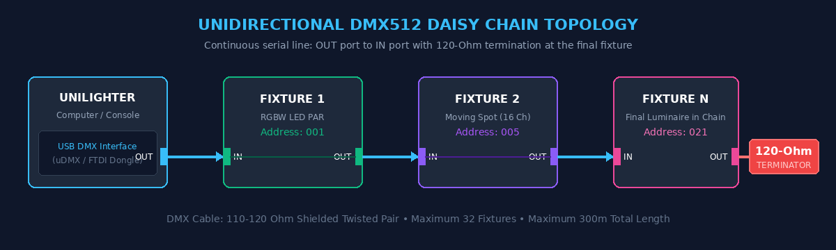
Basic DMX512 control uses a linear multidrop bus. In normal operation, data leaves your console (or USB interface) and travels along one continuous cable: into the DMX IN port of the first fixture, out through its DMX OUT/THRU port, into the next fixture, and so on until the final fixture.
Note
What about RDM? Basic DMX data normally travels from one controller to many receivers. RDM uses the same primary pair for controlled bidirectional communication, but it does not change the recommended physical bus topology.
Two Practical Limits
- 32 fixtures is the traditional safe rule: Technically, the electrical limit is 32 unit loads, not always 32 physical fixtures. A conventional receiver may equal one unit load, while many modern receivers use only 1/2, 1/4, or 1/8 unit load. If you do not know the receiver loading, treating 32 devices as the limit is a sensible field rule.
- 300 meters (1,000 feet) is a practical upper guideline: It is not a universal hard limit guaranteed by the DMX standard. Real usable distance depends on cable, receiver loading, connectors, termination, the transmitter, and the electrical environment. On a difficult stage, split and regenerate the signal much earlier.
2. Connectors: 3-Pin vs. 5-Pin XLR
When plugging in stage lights, you will encounter two different XLR connector styles:

- 5-Pin XLR (XLR-5): The connector specified by the DMX512 standard. It helps keep lighting data separate from common 3-pin audio connections and provides two pins for an optional secondary data link.
- 3-Pin XLR (XLR-3): Widely used in club, DJ, and budget stage lighting because the connectors are smaller and less expensive.
Adapters: Converting Between 3-Pin and 5-Pin
The primary DMX link uses three conductors:
- Pin 1: Shield / Signal Common
- Pin 2: Data 1 -
- Pin 3: Data 1 +
- Pin 4: Data 2 - (optional secondary link)
- Pin 5: Data 2 + (optional secondary link)
Pins 4 and 5 are unused on much ordinary modern stage equipment, but they are not meaningless or universally spare.
For normal equipment using the primary DMX pair, 3-pin and 5-pin fixtures can share the same line through simple passive adapters:
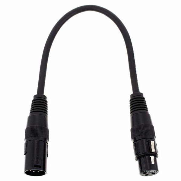
The adapter connects Pin 1 to Pin 1, Pin 2 to Pin 2, and Pin 3 to Pin 3; Pins 4 and 5 remain unconnected. This is reliable for standard primary-pair DMX, but inspect unusual legacy equipment before assuming its extra pins are unused. Keep two adapters in each direction in your gig bag.
Warning
Do Not Confuse XLR-5 with 5-Pin DIN (MIDI)! MIDI connectors have five small pins in a horseshoe pattern. They are mechanically and electrically incompatible with XLR-5. MIDI uses a different opto-isolated current-loop interface, normally around \(5\,\text{mA}\); DMX uses differential EIA-485 signaling.
3. The "Microphone Cable" Trap
Because 3-pin DMX fixtures use the same XLR-3 shell as analog microphones, technicians in a rush often borrow cables from the sound department.
This is a very common cause of intermittent lighting glitches—but the label on the cable is less important than its electrical specifications.
| Metric | Dedicated DMX / Suitable Digital Cable | Ordinary Analog Microphone Cable |
|---|---|---|
| Characteristic Impedance | \(100-120\,\Omega\), with \(120\,\Omega\) preferred | Often roughly \(40-70\,\Omega\) in analog designs that publish the value; it is not standardized for EIA-485 and may be unspecified |
| Conductor-to-Conductor Capacitance | Designed for data; DMX portable cable is specified at \(\leq 65\,\text{pF/m}\) | Varies widely: roughly \(60-165\,\text{pF/m}\) appears in real microphone-cable specifications, with star-quad designs often near the high end |
| Signal Behavior at \(250\,\text{kbit/s}\) | Maintains controlled transmission-line behavior and clean transitions | Impedance mismatch creates reflections; higher capacitance can slow and round transitions |
| Stage Result | Predictable over long, loaded cable runs | May work perfectly on a short run, then become unreliable as length, load, junctions, and interference increase |
Published analog examples show why a range is more honest than one magic number: Belden specifies about \(40\,\Omega\) for its 1804A star-quad microphone cable, \(50\,\Omega\) for 8428, and \(67\,\Omega\) for 8412. Other manufacturers often publish capacitance but do not specify characteristic impedance at all.
Tip
Some “microphone cables” really are suitable for DMX. Digital microphone/AES3 cables and multi-purpose stage cables are commonly built around \(110\,\Omega\). Belden 1800F and Sommer SC-BINARY 225 are examples; Sommer explicitly rates the same cable for microphone, AES/EBU, and DMX use. If a cable has a controlled impedance in the DMX range, suitable capacitance and shielding, there is no fundamental penalty just because somebody also calls it a microphone cable. These cables exist, but they are much less common in a generic box of analog mic leads—check the model and datasheet rather than trusting the connector.
What Does “250 kbit/s” Mean in Frequency Terms?
DMX sends 250,000 bits per second, so one bit lasts \(4\,\mu\text{s}\). The fastest repeating 101010... pattern has a fundamental frequency of about \(125\,\text{kHz}\). Real square-wave edges also contain harmonics extending far above that frequency, which is why a cable that is perfectly adequate for \(20\,\text{kHz}\) audio can still distort DMX transitions.
Why It Fools You in the Warehouse
A generic microphone cable may work in an empty room with one fixture on a 2-meter lead. Problems often appear only when the run grows to 40 meters, more receivers and connectors are added, the end is left unterminated, or the route runs alongside dimmer outputs and power distribution.
Tip
Heavy bass is not an electrical DMX interference source by itself. The DJ starting the music often coincides with the full lighting and power rig coming online, which makes an existing marginal cable run finally reveal itself.
For unknown cables and important shows, use genuine \(100-120\,\Omega\) shielded DMX or compatible digital cable.
4. The 120-Ohm Terminator: Stopping the Echo
When a fast electrical transition reaches the open end of a cable, part of the wave reflects back along the line. The reflection can overlap later transitions and reduce the receiver's noise margin.

What Is a Terminator?
A DMX terminator is a male XLR plug containing a \(120\,\Omega\) resistor, commonly rated around \(0.25-0.5\,\text{W}\), across Pins 2 and 3.
When plugged into the DMX OUT/THRU port of the final fixture, it matches the end of the transmission line and greatly reduces reflections. Real cables, connectors, stubs, and component tolerances are not perfect, so “greatly reduces” is more accurate than promising literally zero reflection.
Note
Some fixtures provide a termination switch or automatic internal termination. Check the fixture manual before adding a second terminator.
5. Active Opto-Splitters vs. the Forbidden "Y" Cable
🚫 The Unreliable Shortcut: Passive "Y" Splitters
Do not use a passive XLR Y-cable to create two DMX branches:
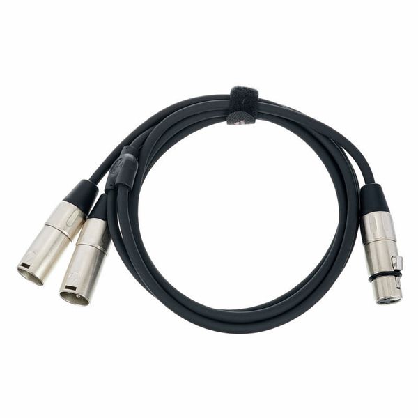
Each outgoing cable still has its own characteristic impedance of roughly \(120\,\Omega\). The problem is the junction: the incoming wave sees two lines in parallel, approximately
\($120\,\Omega \parallel 120\,\Omega = 60\,\Omega\)$
That mismatch creates a strong reflection and two branch ends that must somehow be terminated. A very short Y arrangement may appear to work, but it is unpredictable and can fail after one cable, connector, or fixture changes.
✅ The Professional Solution: Active Opto-Isolated DMX Splitters
Use an active DMX splitter (often called an opto-splitter, buffer, or distributor):
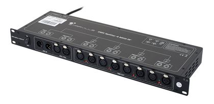
- Independent regenerated lines: Each output starts a new electrical segment with its own unit-load and cable-length budget. Terminate each branch at its final fixture.
- Fault containment: Galvanic isolation helps stop ground-potential differences, surges, and faults on one branch from propagating into the controller or other branches. The protection is limited by the splitter's specified isolation and protection ratings; it is not a universal guarantee against any mains fault.
📝 Self-Assessment Quiz
-
Scenario A: A line of eight moving heads is stable during setup, but the last two occasionally jerk and flash during the show. The final
DMX OUThas nothing connected. What should you check first, and what fixture feature could mean an external terminator is unnecessary? -
Scenario B: A technician says, “I've used microphone cables for lighting dozens of times and they worked.” How would you explain both why that can be true on small rigs and why a generic analog mic lead is still a poor choice for a long DMX run? What cable specification would make a microphone-labelled cable genuinely suitable?
-
Scenario C: You have fixtures on Stage Left and Stage Right. Why is a passive XLR Y-cable unreliable even though both outgoing cables are individually \(120\,\Omega\), and what should you use instead?