2D & 3D Console Visualizer
The console visualizers preview your project's fixtures, light output and stage objects. Both views edit the same console scene, saved with the project. Site Planner plans are stored independently: console fixture placements do not automatically become Site Planner placements.
Open fixture controls
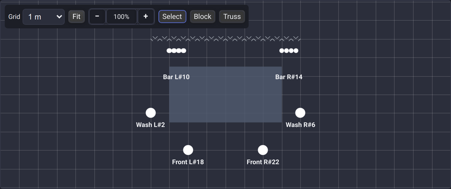
Click a fixture in the 2D visualizer to open its Device Control screen. This works in Compact View and in Grid View with the Select tool. Dragging a fixture in Grid View changes its position without opening controls.
In the 3D Visualizer inspector panel, click a fixture body to open its controls. Camera drags and Shift/Ctrl/Meta clicks do not open controls; modifier clicks keep multiple-fixture selection available. On the full Visualizer page, 3D transform tools keep clicks available for selecting and editing fixtures.
Fixture clicks do not open controls in the embedded demo.
Edit the 2D scene
Open Visualizer in Grid View; embedded previews retain Compact View. Choose a grid spacing of 1, 0.5 or 0.25 metres. Grid changes affect snapping without rescaling or moving existing fixtures. Negative coordinates are supported; Fit frames fixtures and visible objects wherever they are placed.
Choose Block and drag a rectangle to draw a stage box, or Truss and drag a segment for a horizontal truss. In Select mode move objects, resize a block with its handle, adjust a truss with its endpoint handles, or turn either object with its rotation handle. The property bar edits position, elevation, dimensions and rotation numerically. Confirm a typed number with Enter or by leaving its field; arrow steps apply immediately. Selecting another object discards an unconfirmed draft, so it cannot change the newly selected object.
Elevation is the object's centre height. New blocks are 0.5 m tall with their base on the floor; new horizontal trusses have a 0.25 m square section at 6 m elevation. Delete removes a selected object. Escape or pointer cancellation restores an unfinished edit or discards an unfinished drawing. Editing a tilted stage box in 2D keeps its 3D tilt/elevation unless explicitly changed.
Zoom and move the 2D view
In Grid View, use − and + to change the scale in 10-percentage-point steps, from 20% to 300%. Buttons zoom around the centre of the view. Click the percentage to return to 100% around the current centre; Fit frames all fixtures and visible stage objects again and sets 100%.
- Scroll with a mouse wheel or trackpad to move the view. Trackpad scrolling supports both axes; Shift + vertical scroll moves horizontally.
- Hold Ctrl or ⌘ while scrolling, or pinch the trackpad, to zoom around the pointer. Add Shift for finer zoom adjustments.
- On a phone, tablet or touchscreen, use two fingers to move the view and pinch to zoom. One finger retains the normal fixture and object editing actions. Adding a second finger cancels and restores an unfinished edit before moving the view; lifting one finger does not resume editing.
Fixture symbols, source spacing, labels and stage objects scale together. The toolbar and editing handles remain usable at every zoom level. Zoom and scrolling do not change saved object coordinates or grid snapping. Resizing the view keeps its centre and scale; use Fit if you want to frame the scene again.
The view position and zoom are temporary and are not saved in the project. Entering Grid View starts with Fit. Compact View keeps its existing layout and scrolling behaviour.
Edit and preview in 3D
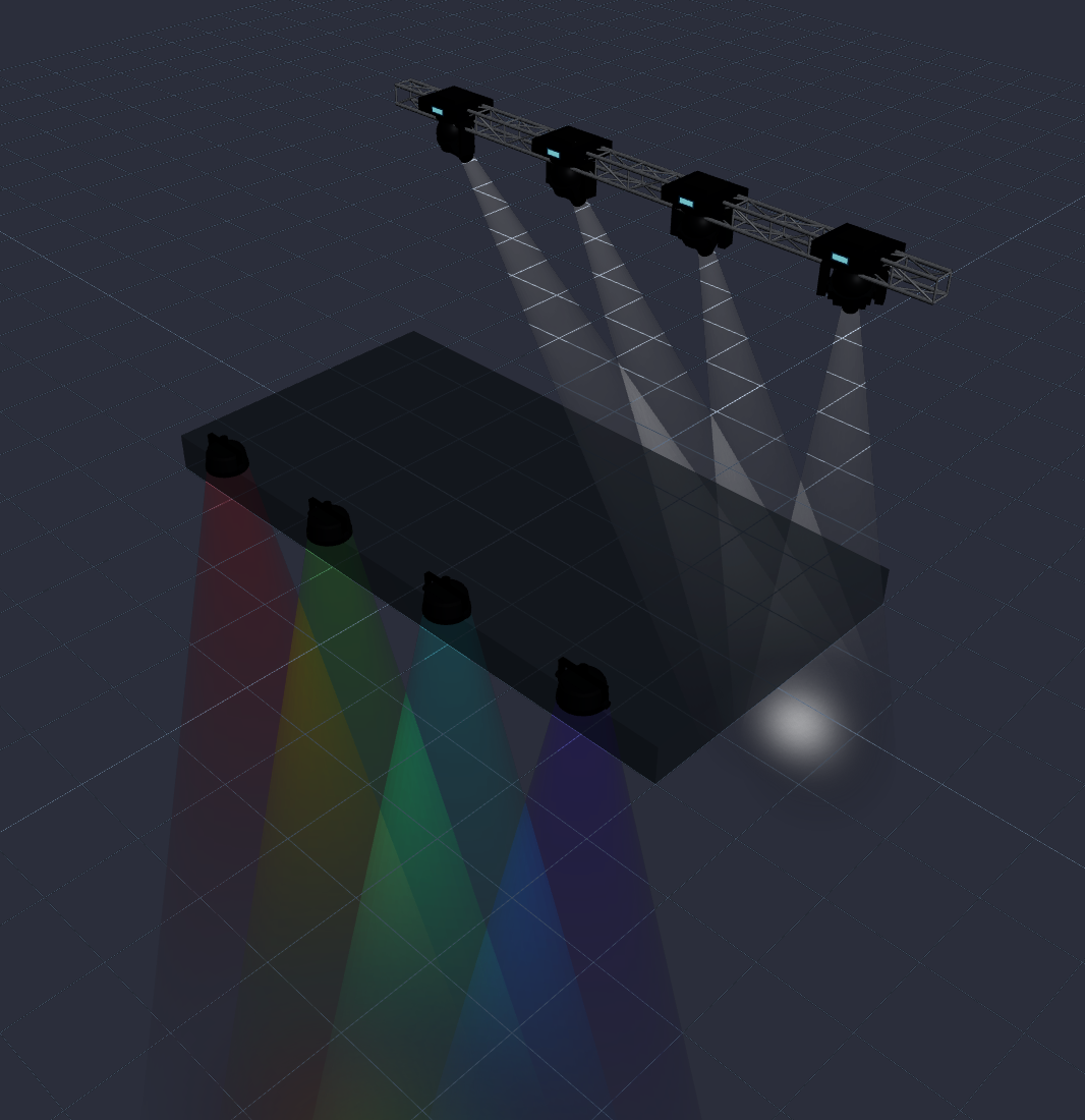
Select stage boxes and trusses independently. Stage boxes support translation, rotation and scaling; trusses support translation, horizontal rotation and scaling along their length. The configuration panel edits object properties. Changes appear in both views and are included in the project save.
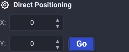
For a single selected fixture in Edit mode, use Direct Positioning to enter X and Y, then click Go. Confirm typed numbers with Enter or by leaving each field; arrow keys and step buttons apply a step immediately.
Imported physical data can supply dimensions, pan/tilt travel, beam data, white temperature, geometry and independent light sources. Availability depends on the profile: a generic model is not a measured replica of the actual fixture. Profile and per-device model settings determine the representation; fog fixtures have a dedicated 2D symbol.
Compatible Strobe/Shutter settings control visible flashes and blackout. A closed shutter hides light rather than the fixture body. Preview frames do not themselves send DMX.
The 2D view indicates the selected flash rate with regular flashes for every mode. It does not reproduce a fixture's Random, Pulse or Ramp pattern; confirm the real effect with the fixture and its manual. Individual Head and shared strobe stages at the same rate stay in phase within the preview, even when enabled separately. Hidden 2D previews pause to keep the console responsive.
Physical emitters and segmented colors
Emitter Layout separates logical control Heads from physical sources. Both views use the same local source positions and bindings. Compact View fits arrangements inside bounded cards; Grid View projects local positions through the mounting rotation and Fit includes the outer emitters. Circular symbols and beams can show independent color sectors; uniform LED bars can use rectangular apertures and beams. Configure a single instance in its 3D configuration panel, or set shared defaults in Fixture Editor.
More separate emitters mean smaller Grid View symbols and estimated 3D bodies. Automatic spacing also becomes tighter when no spacing or fixture width is configured: 16 sources use a quarter of the single-source size and an estimated 0.225 m center spacing. Measured dimensions, manual spacing, Custom coordinates and imported geometry are preserved; beam length and angle stay unchanged. A single optic containing multiple color segments keeps its normal size. Individual Head labels are hidden above eight sources and on narrow Grid View screens; source identifiers remain available on hover.
Coordinates and older projects
The 2D ground-plane position maps to the 3D ground plane; fixture height is the vertical coordinate. Stage-object elevation uses the same real-world metric scene. Older projects receive missing scene defaults while existing recorded positions and stage-box transforms remain intact. Fixtures without explicit geometry use the improved automatic emitter layout and corrected mounting rotation, so their source arrangement can change from the former square/triangle fallback. Lighting programming is preserved.
Save the project to retain fixtures, stage boxes, trusses and grid spacing. Use Site Planner separately for venue plans, mounting, variations and plan sheets. Use Movement, Scenes or Animations to drive lighting looks in the console scene.