Lesson 5.3: Choreography Timelines & Pixel Arrays
Warning
⚠️ Draft Lesson: This lesson is currently a working draft and is undergoing practical review. Technical labs, workflows, and diagrams may be expanded and refined in upcoming revisions.
In modern stadium and arena productions, physical lighting fixtures are no longer just discrete spotlights pointed at performers. High-density arrays of LED pixel battens, multi-cell strobe tubes, and moving wash rings cover trusses and stage backdrops, forming vast luminous structures containing thousands of individually controllable RGB emitters.
Attempting to animate 2,000 discrete LED cells using traditional single-channel faders or linear keyframe timelines is practically impossible: a single look would require tweaking 6,000 DMX parameters.
To command high-density arrays intuitively, modern show control treats the lighting rig as a spatial volumetric display surface. Instead of animating channels numerically, you paint graphics, project procedural waves, and animate raster paths across a 2D stage canvas, which physical fixtures sample in real time.
In Unilighter, this spatial engine is the Choreography Editor.
In this lesson, we explore spatial emitter mapping, dissect multi-parameter canvas maps, master procedural wave generators, and learn how to project fluid visual dynamics across stadium-scale pixel matrices.
1. The Spatial Paradigm: Lighting Fixtures as Physical Pixels
The spatial matrix paradigm shifts how we think about lighting control:
| Dimension | The Linear Channel Paradigm (Legacy) | The Spatial Matrix Paradigm (Unilighter) |
|---|---|---|
| Mental Model | Numerical channel rows: Channel 101 AT 80 ENTER. |
A 2D virtual coordinate grid \((X, Y)\) representing the physical stage layout. |
| Control Unit | An isolated DMX parameter on a specific fixture. | A physical emitter sampling a pixel value from a virtual canvas. |
| Animation Method | Keyframing individual channel values on separate timelines. | Projecting visual media, gradients, and procedural wave generators across the canvas. |
| Scalability | Becomes unmanageable beyond 50 fixtures. | Effortlessly scales to thousands of LED pixels across dozens of universes. |
+-------------------------------------------------------------------------+
|                  THE CHOREOGRAPHY SAMPLING ENGINE                       |
+-------------------------------------------------------------------------+
|                                                                         |
|  [Virtual 2D Canvas]                                                    |
|  Procedural Wave / Raster Graphic / Color Gradient                      |
|                                                                         |
|         (x: 10, y: 20)           (x: 30, y: 20)          (x: 50, y: 20) |
|               │                        │                       │        |
|               ▼                        ▼                       ▼        |
|        [Sampler Point]          [Sampler Point]         [Sampler Point] |
|               │                        │                       │        |
|               ▼                        ▼                       ▼        |
|      Physical Fixture 1       Physical Fixture 2      Physical Fixture 3|
|      (Overhead Left)          (Overhead Center)       (Overhead Right)  |
+-------------------------------------------------------------------------+
2. Emitter Mapping in the Choreography Editor
Opening the Choreography Editor (/#/choreography) reveals Unilighter’s dedicated spatial workspace:
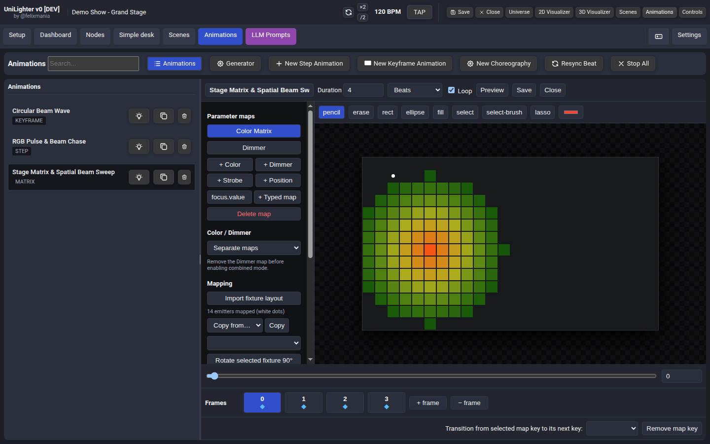
2.1 Bridging Physical Stage to Virtual Pixels
At the core of the engine is Emitter Mapping:
- Physical Heads to Virtual Coordinates: Each physical fixture (or individual multi-head cell on an 8-pixel LED batten) is assigned a discrete coordinate \((X, Y)\) on the pixel grid.
- Import Fixture Layout: Clicking the Import fixture layout button automatically reads the physical \((X, Y, Z)\) positions of your lights from the 2D Site Planner or 3D Stage Visualizer and projects them onto the canvas, preserving your exact physical truss geometry.
- Visual Health Indicators:
- White Dot: Successfully mapped emitter ready to render the active parameter map.
- Red Dot: Incompatible emitter (e.g. attempting to map a dimmer-only blinder onto a Color Map).
- Transform Tools:
- Rotate 90°: Rotates fixture emitter orientations (essential when switching between horizontal ceiling bars and vertical floor towers).
- Nudge (
←,→,↑,↓): Micro-adjust individual fixture emitter positions on the canvas.
3. Multi-Parameter Spatial Maps
The Choreography Editor is not limited to color video mapping. A single choreography project can run multiple synchronized parameter layers simultaneously:
| Parameter Map | Data Type | Stage Control Mechanism |
|---|---|---|
| Color Map | color |
2D HSV / RGB color mixing. Output is automatically translated to each fixture’s physical diode profile (RGB, RGBW, RGBL, or CMY). |
| Dimmer Map | scalar |
High-speed intensity gradients, traveling wave washes, and master brightness masks (\(0.00 - 1.00\)). |
| Strobe Map | scalar |
Spatial strobe pulses, radial flash bursts, and localized blinder accents. |
| Position Map | position |
Modulates motorized Pan and Tilt coordinates based on canvas pixel values. |
| Custom Typed Map | scalar |
Modulates any physical optical parameter (e.g. zoom.value, focus.value, or prism.value) across the spatial array. |
4. Procedural Spatial Wave Generators
Instead of manually drawing every frame, Unilighter provides real-time Procedural Generators that calculate fluid mathematical motion across the 2D array:
[Procedural Generator] ──> [Mathematical 2D Matrix] ──> [Emitter Samplers] ──> [DMX Output]1. The Directional Sweep (Sweep)
A linear gradient traveling across the stage at an adjustable trajectory angle (direction: 0° - 360°) and velocity:
- Set
direction: 90°for a vertical wash cascading from the ceiling down to the floor. - Set
direction: 0°for a wave traveling from stage left to stage right.
2. The Continuous Sinusoidal Wave (Wave)
Generates smooth undulating harmonic waves. Ideal for creating continuous oceanic or liquid lighting effects across stadium arrays without sudden visual edges.
3. The Radial Shockwave (Radial)
An expanding or contracting circular ripple radiating outward from a configurable origin coordinate \((cX, cY)\):
- Anchor \((cX, cY)\) at the center of the stage where the lead singer stands.
- On the kick drum or drop, trigger an expanding radial pulse: a ring of light sweeps outward from the singer, across the backline, and into the stadium wings like an optical shockwave.
4. Fractal Noise (Noise)
Generates multi-octave Perlin / Simplex procedural fractal noise with adjustable Speed, Softness, and Seed:
- Produces organic, evolving visual textures that simulate natural phenomena like flickering campfires, undulating aurora borealis, or moving clouds.
- Because it is mathematical noise, the pattern never repeats identically.
5. Raster Motion & Keyframe Baking
When a production requires explicit graphic elements—such as a flying cross, a corporate logo silhouette, or a bouncing light chevron—the Raster Motion system provides keyframe animation:
- Draw the Sprite: Use the Pencil, Rectangle, Ellipse, or Fill tool to paint a graphic shape onto the canvas.
- Lift Selection: Use the Select or Lasso tool to encircle the shape, then click Lift cut or Lift copy to detach the pixels into a floating raster sprite.
- Keyframe Motion: Move the playhead along the timeline, reposition the floating sprite, and click Add motion key @ playhead.
- Looping: Enable Ping-pong to make the sprite bounce back and forth smoothly across the fixture array.
- Bake to Keys: Click Bake to raster keys to compile the continuous motion path into discrete raster keyframe frames for instant, rock-solid playback.
6. Hands-On Lab: Building an Outward Radial Shockwave
Follow this step-by-step lab to create and preview an outward radial shockwave across an array of fixtures:
Step 1: Open the Choreography Editor
- In Unilighter, navigate to Choreography (
/#/choreography). - Click Create Project and name it
Stadium Radial Shockwave.
Step 2: Map Your Fixtures
- In the left panel, click Import fixture layout.
- Select your overhead and floor fixtures (e.g. 16 moving wash lights or LED bars).
- Verify that the white emitter dots appear distributed across the canvas, representing your physical stage layout.
Step 3: Add a Radial Generator
- In the toolbar, click Add Generator and select Radial.
- In generator settings:
- Set
Center XandCenter Yto0.50(placing the origin point dead center of the stage). - Set
Speedto1.2 Hz(fast explosive expansion). - Set
Softnessto0.30(giving the wave crest a clean, punchy leading edge with a smooth tail).
- Set
Step 4: Configure Color Integration
- Switch to the Color Map tab.
- Pick a dual-color palette: set the background to Deep Indigo (\(240^\circ\)), and set the expanding wave crest to Electric Cyan (\(180^\circ\)).
- Toggle Color Controls Dimmer on, so the wave crest punches brightness up to \(100\%\) as it expands.
Step 5: Verify in the 3D Visualizer
- Click Play on the Choreography transport.
- Open the 3D Stage Visualizer (
/#/visualizer). - Watch the physical beams in 3D virtual space: a vibrant circular shockwave ripples outward from stage center across the entire rig in rhythmic sync with your tempo!
📝 Self-Assessment Quiz
Test your comprehension of spatial matrix control and choreography timelines:
- Scenario A: A lighting programmer is tasked with animating a chasing color wave across forty 8-pixel LED battens (totaling 320 RGB cells across 6 DMX universes). Attempting to program this on a traditional console requires creating dozens of cue steps and adjusting hundreds of channel faders. What is the modern architectural solution in Unilighter?
- A) Soldering a 120-ohm resistor across the data line of every fourth LED batten.
- B) Using the Choreography Editor to map the 320 physical emitters onto a 2D virtual canvas and driving them simultaneously with a procedural
SweeporWavegenerator. - C) Inverting the binary DIP switch 10 on all forty fixtures to force them into standalone audio-reactive chase mode.
- D) Lowering the console's Ethernet network refresh rate to 5 Hz to reduce programming complexity.
Correct Answer: B Why this is correct: The Choreography Editor abstracts hundreds of discrete multi-cell channels into a 2D spatial canvas. Emitters sample procedural wave generators directly, creating fluid, synchronized multi-universe chases with zero channel-by-channel coding. Why other options are incorrect: Resistors (A) terminate RS-485 transmission lines; DIP switch standalone modes (C) disable console control; and throttling network refresh rates (D) degrades show quality without helping programming.
- Scenario B: In Unilighter's Choreography Editor, what is the role of the "Import fixture layout" function?
- A) It downloads open-source 3D CAD models of luminaires from manufacturer cloud servers over the Internet.
- B) It automatically reads the physical \((X, Y, Z)\) coordinates of patched fixtures from the 2D Site Planner / 3D Visualizer and positions virtual emitter sampling dots on the canvas to match the physical stage layout.
- C) It calculates the total AC kilowatt power load and neutral conductor triplen harmonic heating.
- D) It automatically assigns sequential binary DIP switch addressing to avoid DMX channel overlaps.
Correct Answer: B Why this is correct: "Import fixture layout" bridges real-world physical geometry with virtual pixel coordinates: it imports fixture positions from the stage planner so that graphics projected onto the canvas match the physical layout on trussing. Why other options are incorrect: The function does not download CAD files from cloud servers (A); electrical load and harmonic calculations are power engineering tasks (C); and DIP switch addressing is configured in Device Patch (D).
- Scenario C: What distinguishes a procedural
Noisegenerator from a static pre-rendered graphic loop in spatial matrix lighting design?- A) Procedural noise draws \(50\times\) more electrical current from the venue's three-phase mains distribution panel.
- B) Procedural noise calculates multi-octave fractal mathematical curves (such as Perlin or Simplex noise) in real time, producing evolving organic patterns that never repeat identically, whereas pre-rendered loops cycle predictably.
- C) Pre-rendered loops can only display monochrome tungsten amber, whereas procedural noise can only output ultraviolet blacklight.
- D) DMX512 standards prohibit transmitting procedural noise across more than one universe.
Correct Answer: B Why this is correct: Procedural fractal noise evaluates mathematical equations continuously, generating fluid, non-repeating organic dynamics (resembling natural fire, water, or clouds) without the mechanical predictability of static video loops. Why other options are incorrect: Math calculations happen on the computer CPU/GPU, having zero effect on fixture AC power consumption (A); procedural noise works with any color space (C); and DMX512 transmits numerical slot values regardless of how software generated them (D).